This is the first part of a multi-part tutorial that we are working on for you to get started with the Simple Labs Quick Start kit for Arduino. In this part, we will see how to connect the following components of the Quick Start Kit and Program for them using the Arduino. We will not delve into arduino programming as this has been covered again and again.
- LED
- RGB LED
- Push Button
- Trimpot
- LM 35 - Temperature Sensor
- LDR - Light sensor
- Transistor 2N2222A + Buzzer
For this tutorial we will choose a simple activity for each element and keep adding to the previous activity. Keep in mind we are saying activity and not project as we are not building any project of great significance, we are rather focusing on 'how to'. You are expected to go step by step through the activities as some of the coding might build on the previous activity. So , Lets get started!
Download the following zip file with the source code for all these examples.
Quick_Start_Kit.zip
Download the following zip file with the source code for all these examples.
Quick_Start_Kit.zip
The Breadboard
The Breadboard is a simple construction base for building circuits without soldering. you can plug in different components and plug in wires between them. The top two rails and the bottom two rails are called the power rails and these are marked with a '+' and '-' symbol. These are connected as rows. Each row of connection consists of 5 groups of 5 points each per group. There is no connection between the 5th and the 6th group so the points is group 1 to 5 are connected and the points in group 6-10 are connected. we can connect a wire between any 2 two points of these groups and get them all connected. [This could be confusing if you have never used a breadboard before, we will try and make it easier soon!]
We would need to get all our '+' lines connected to each other and then do the same for the '-' lines. This will make it easy for us to connect various components. Its a good practice stick to color coding for wires. Use red colored wires whenever you connect something to '+' ve, black colored wires whenever you connect something to '-' ve and blue colored wires whenever you are connecting between components.
So first set up the breadboard as in the following images
 |
| First Like This |
 |
| Then Like This |
 |
| Final Finished Setup |
LEDs (Light Emitting Diodes) are the
most commonly used of electronic components. They are everywhere –
torches, displays, indicators, etc. Every project will eventually end
up having atleast one led. The Official Arduino Boards and most of
the Clones do come with an on-board LED which you can try with the
default blink program found in the File->Examples->Basic menu
of Arduino IDE.
So How to Connect a LED?
The Long of the LED is the Anode (Positive Terminal!) and the short led is the Cathode(Negative Terminal).
 |
| The Terminals of the LED |
 |
| Place the LED as shown |
 |
| Place a Current Limiting Resistor (too much current passing through an LED can burn it!) between the negative terminal of the LED and the '-'ve terminal on the power rail (we will soon connect this to the '-'ve (aka ground) of our Arduino Board!) |
 |
| Take a wire from the pin marked 'GND' of your arduino and connect it to the '-'ve power rail of the breadboard. Now all points of the '-' ve power rail will be connected to the ground of the arduino! |
 |
| Next, Connect a wire between the 11th pin of the arduino(yes the 11th pin and not the 13th pin!) and the positive terminal of the LED. This is going to be our control line for the LED |
Programming to control the LED
So how can you control a LED? Well there are only 2 ways to control an LED. you can either switch it ON / OFF or you can control the intensity with which it glows (Very much like a fan!). So lets see how to do the first control - ON/OFF (we can call this digital control! Very much 0s & 1s)
Try the following code. [Blink.ino]
 /*
  Blink
  Turns on an LED on for one second, then off for one second, repeatedly.
  This example code is in the public domain.
  */
 void setup() {
  // initialize the digital pin as an output.
  // We have our LED connected to Pin 11
  pinMode(11, OUTPUT);     // Sets the 11th pin as an Output pin
 }
 void loop() {
  digitalWrite(11, HIGH);  // set the LED on
  delay(1000);       // wait for a second
  digitalWrite(11, LOW);  // set the LED off
  delay(1000);       // wait for a second
 }
Next, Lets see how to control the intensity of the LED.
The Intensity can be varied by controlling the voltage applied to the individual pins. If you take a look at the 11th PIN on the arduino, you would see a marking 'PWM' next to it (Remember we connected our LED to the 11th pin). The PWM pins in addition to generating digital HIGH / LOW signals can generate analog voltages between 0 & 5.
The PWM Pins
[Pins 3,5,6,9,10,11] that can generate a PWM signal of 8-bit
resolution.[8-bits can represent a maximum value of 255, and a 8-bit
resolution here means that 5 volts is represented by 255 divisions. So
if you want to generate 1 volt, you would use the value 51]
The analogWrite function will take a 8-bit numerical value as a parameter [called duty cycle] and produce an output voltage corresponding to this value. It will set the pin to generate a steady square wave of the specified duty cycle at roughly 490Hz frequency.
Finally, when using a pin in the PWM mode, we don't have to use the pinMode() function.
Try the following code with the same setup and see how the intensity increases and decreases...[Intensity.ino]
The RGB LED
The RGB led aka the tricolor led is a led that can help generate a multitude of colors by mixing red, blue & green colors. Its more like 3 leds (red, green & blue) put together into a single led.
It has 4 pins with 1 of the pins being a common cathode and the other 3 pins acting as anodes for the 3 different colours. by varying the intensity of each of the 3 colours individually, we can generate various colours. This led is the same as 1 pixel of a LED TV!.
Heres how to wire it up
Now try the following code first. This code is a normal digital control of all the three colors separately.[RGB_Blink.ino]
Next Lets get generating Colors, try the following code. Play around with the values and get yourselves comfortable.[RGB.ino]
Push Buttons like LEDs form a common part of most electronics devices. Push buttons can be used to get user feedback. (image a common scenario of scrolling through a menu and selecting an option - there are buttons all around the process!)
So Far we have not used the SUPPLY voltage from the Arduino however, for connecting the button, we would need this. So, before connecting the Button, we need to connect our '+'ve terminal to the 5Volts SUPPLY line on the Arduino. Connect as shown in the image below.

There are 2 ways to connect a Push Button to the arduino - the Pull-Down Configuration & the Pull-Up Configuration. We will take a look at both these.
The Pull-Down Cnfiguration
In this configuration the Push Button is set-up such that it keeps giving a constant LOW signal(0) when not being pressed and gives a HIGH signal(1) when being pressed. To ensure that it keeps giving a LOW signal at all times, the Input line is also connect to the '-'ve terminal through a resistor. So in when the button is not being pressed, the input line stays connected to the GROUND. When the button is being pressed (and as the path of low resistance is always preferred) the input line gets connected to the SUPPLY line. Look at the following image to see how to connect a button in this configuration. We will keep this connection only as a reference as we will be using the Pull-Up configuration for our circuits.
The Pull-UP Cnfiguration
In this configuration the Push Button is set-up such that it keeps giving a constant HIGH signal(1) when not being pressed and gives a LOW signal(0) when being pressed. To ensure that it keeps giving a HIGH signal at all times, the Input line is also connect to the '+'ve terminal through a resistor. So in when the button is not being pressed, the input line stays connected to the SUPPLY . When the button is being pressed (and as the path of low resistance is always preferred) the input line gets connected to the GROUND line. Look at the following image to see how to connect a button in this configuration. This is the most preferred method to connect a button.
Now try the following code, Pressing the Button increases the intensity of one colour at a time, once the maximum intensity of the colour is reached that colour is set to 0 and the intensity of the next colour starts increasing [ RGB_Button.ino]

Trimpot
Trimpots are used for getting variable / adjustable user inputs. Common example of a trimpot is the volume knob of your stereo player, Tuning knob of the radio, etc.
A Trimpot aka variable resistor has three pins and an adjustment screw. A Trimpot acts as a potential divider and gives an output voltage on the 2nd pin. This output voltage is in-between the voltages supplied to the 1st and 3rd pins. The output voltage can be varied by adjusting the screw. The 1st and 3rd pins are connected to SUPPLY / GROUND and the middle pin is connected to Analog Input 0 on the arduino using a wire.
Connect the trimpot as shown in the images below
The Analog Input pins on the Arduino let you connect sensors and other analog devices like trimpots that product a voltage output in the range of 0-5 volts. The Analog input on Arduino is of 10-bit resolution. 10-bit
resolution means that the Voltage range of 0-5 Volts is represented in
1024 steps from 0-1023. So you would be reading an input value in the
range of 0-1023 where 1023 would correspond to 5 Volts
Arduino[the IDE!] comes with a serial library that can be used to transmit data serially to a computer. We shall make use of this library to transmit our trimpot value to a Computer every 1 second. You can open the 'Serial Monitor' in the Arduino IDE to view these values. You can open the 'Serial Monitor' by going to the 'Tools' menu. When using the 'Serial Monitor' ensure that the baud rate selected is the same as the one used in the program.
Try the following program and see the values you get by varying the trimpot [ simple_trimpot.ino]
Try the following program [RGB_button_trimpot.ino]

Working with Sensors - LM35
So lets get started with some sensors, LM35 is a simple temperature sensor. LM35 has 3 pins. Refer to the following image for the pin mappings
Now time for the program. Try the following program. Pressing the Button changes the current active color of the RGB LED & prints the current temperature value to the Serial Monitor and varying the trimpot changes the intensity of the color [RGB_button_lm35.ino]
LDR - Light Dependent Resistor - A Simple Light Sensor
The LDR is a variable resistor, whose resistance varies based on the light incident upon it. More the light, less the resistance. Now the LDR cannot be used directly. We would need to convert the change in resistance of the ldr to change in voltage. We can achieve this by constructing a potential divider using the ldr and a fixed resistor. Then we can take the output of the potential divider and connect it to an Analog In pin on the arduino.
Follow the images below and connect the LDR
Try the following Code [RGB_button_ldr.ino]
Next lets see how we can generate sound using a Buzzer. The Buzzer would require more current than provided by the pins of the arduino. To provide the buzzer with more current, we shall use a transistor to trigger the buzzer. The transistor in turn will be triggered by a pin on the arduino. If you do not know about transistors, its advisable you check it out http://en.wikipedia.org/wiki/Transistor
Here's what our Transistor 2N2222A looks like
Try the following code where the Buzzer stays on as you keep pressing the Button in our previous program [RGB_button_ldr_buzzer.ino]
 /*
  Intensity
  Increases the Intensity of a LED from 0 to maximum and on reaching maximum
  starts decreasing back to 0
  */

 int intensity = 0;

 void setup() {

 }
 void loop() {

   while(intensity < 255) // Check if intensity has reached maximum value, if yes then exit the loop
   {
     analogWrite(11,intensity);
     delay(25);
     intensity++;
   }

   while(intensity > 0) // Check if intensity has reached minimum value, if yes then exit the loop
   {
     analogWrite(11,intensity);
     delay(25);
     intensity--;
   }

 }
The RGB LED
The RGB led aka the tricolor led is a led that can help generate a multitude of colors by mixing red, blue & green colors. Its more like 3 leds (red, green & blue) put together into a single led.
It has 4 pins with 1 of the pins being a common cathode and the other 3 pins acting as anodes for the 3 different colours. by varying the intensity of each of the 3 colours individually, we can generate various colours. This led is the same as 1 pixel of a LED TV!.
Heres how to wire it up
 |
| Pin Mappings of the RGB LED |
 |
| Place resistor between the common cathode and the '-'ve terminal |
 |
| Connect RED to Pin 11, Blue to Pin 10 & Green to Pin 9 on the Arduino (these are PWM pins) |
/*
  RGB_Blink
  Turns on each of the color spectrums for 4 seconds, repeatedly.
  */

void setup() {
  // initialize the digital pins as an output.
  pinMode(11, OUTPUT);
  pinMode(10, OUTPUT);
  pinMode(9, OUTPUT);
}

void loop() {
  digitalWrite(9,LOW);
  digitalWrite(11, HIGH);
  delay(4000);
  digitalWrite(11, LOW);
  digitalWrite(10, HIGH);
  delay(4000);
  digitalWrite(10, LOW);
  digitalWrite(9, HIGH);
  delay(4000);
}
Next Lets get generating Colors, try the following code. Play around with the values and get yourselves comfortable.[RGB.ino]
/* RGB

 Sets some random intensity value to the various colours of the RGB LED

 */


 void setup()
 {
 }
 void loop()
 {
  analogWrite(11,153);// Setting the voltage for Blue to around 3 Volts
  analogWrite(10,51);// Setting the voltage for Red to around 1 Volt
  analogWrite(9,51);// Setting the voltage for Green to around 1 Volt
 }
The Push Button
Push Buttons like LEDs form a common part of most electronics devices. Push buttons can be used to get user feedback. (image a common scenario of scrolling through a menu and selecting an option - there are buttons all around the process!)
 |
| Working of a Push Button |
So Far we have not used the SUPPLY voltage from the Arduino however, for connecting the button, we would need this. So, before connecting the Button, we need to connect our '+'ve terminal to the 5Volts SUPPLY line on the Arduino. Connect as shown in the image below.

There are 2 ways to connect a Push Button to the arduino - the Pull-Down Configuration & the Pull-Up Configuration. We will take a look at both these.
The Pull-Down Cnfiguration
In this configuration the Push Button is set-up such that it keeps giving a constant LOW signal(0) when not being pressed and gives a HIGH signal(1) when being pressed. To ensure that it keeps giving a LOW signal at all times, the Input line is also connect to the '-'ve terminal through a resistor. So in when the button is not being pressed, the input line stays connected to the GROUND. When the button is being pressed (and as the path of low resistance is always preferred) the input line gets connected to the SUPPLY line. Look at the following image to see how to connect a button in this configuration. We will keep this connection only as a reference as we will be using the Pull-Up configuration for our circuits.
 |
| The Pull-Down Configuration |
In this configuration the Push Button is set-up such that it keeps giving a constant HIGH signal(1) when not being pressed and gives a LOW signal(0) when being pressed. To ensure that it keeps giving a HIGH signal at all times, the Input line is also connect to the '+'ve terminal through a resistor. So in when the button is not being pressed, the input line stays connected to the SUPPLY . When the button is being pressed (and as the path of low resistance is always preferred) the input line gets connected to the GROUND line. Look at the following image to see how to connect a button in this configuration. This is the most preferred method to connect a button.
 | |
| The Pull-Up Configuration |
/*
  RGB_Button
  Pressing the Button increases the intensity of one colour at a time, once the maximum intensity of the colour is reached
  that colour is set to 0 and the intensity of the next colour starts increasing
 */

int intensity = 0, pin = 9;

void setup() {
pinMode(2,INPUT); // This is the pin to which we have connected the button
}

void loop() {
  if(digitalRead(2)==0) // check if the button is being pressed
  {
    Serial.println("here");
    if(intensity < 255)
    {
    intensity++;
    }
    else
    {
      intensity=0;
      analogWrite(pin,intensity);
      if(pin<11)
        pin++;
      else
        pin=9;
    }
    analogWrite(pin,intensity);
  }

}
Here's the Output

Trimpot
Trimpots are used for getting variable / adjustable user inputs. Common example of a trimpot is the volume knob of your stereo player, Tuning knob of the radio, etc.
A Trimpot aka variable resistor has three pins and an adjustment screw. A Trimpot acts as a potential divider and gives an output voltage on the 2nd pin. This output voltage is in-between the voltages supplied to the 1st and 3rd pins. The output voltage can be varied by adjusting the screw. The 1st and 3rd pins are connected to SUPPLY / GROUND and the middle pin is connected to Analog Input 0 on the arduino using a wire.
Connect the trimpot as shown in the images below
 |
| The Trimpot - See the markings for pins |
 |
| Place the trimpot as shown |
 |
| Connect a wire between pin 1 of the trimpot and the '+'ve terminal |
 |
| Connect a wire between pin 3 of the trimpot and the '-'ve terminal |
 |
| Connect a wire between pin 2 of the trimpot and the Analog In 0 of the Arduino |
 |
| Here is the connection going to the Analog In 0 |
Arduino[the IDE!] comes with a serial library that can be used to transmit data serially to a computer. We shall make use of this library to transmit our trimpot value to a Computer every 1 second. You can open the 'Serial Monitor' in the Arduino IDE to view these values. You can open the 'Serial Monitor' by going to the 'Tools' menu. When using the 'Serial Monitor' ensure that the baud rate selected is the same as the one used in the program.
Try the following program and see the values you get by varying the trimpot [ simple_trimpot.ino]
/*
  A Simple Program to display the value read from the trimpot onto the Serial Monitor
 */

int intensity = 0;

void setup() {
Serial.begin(9600);
}

void loop() {
  intensity = analogRead(0);
  Serial.print("Current Value:");
  Serial.print("   ");
  Serial.println(intensity);
}
If you notice, you will see values from 0-1023. Now we are going to use the trimpot as part of our previous experiment. We will use the button to select the active color of the RGB LED and then use the trimpot to set the intensity of that color. Remember that this would involve scaling 0-1023 to 0-255 (or divide by 4!)
Try the following program [RGB_button_trimpot.ino]
/*
  Pressing the Button changes the current active color of the RGB LED and varying the trimpot changes the intensity of the color
 */

int intensity = 0, pin = 9;

void setup() {
pinMode(2,INPUT);
Serial.begin(9600);
}

void loop() {
  if(digitalRead(2)==0) // Switch being pressed
  {
     if(pin<11)
        pin++;
      else
        pin=9;
     analogWrite(9,0);
     analogWrite(10,0);
     analogWrite(11,0);
  while(digitalRead(2)==0);
  delay(100);
  }
  intensity = analogRead(0)/4; // Scaling the input resolution to match with our output resolution.
  analogWrite(pin,intensity);
  Serial.print(pin);
  Serial.print("   ");
  Serial.println(intensity);
}
Heres the final setup and the output!

Working with Sensors - LM35
So lets get started with some sensors, LM35 is a simple temperature sensor. LM35 has 3 pins. Refer to the following image for the pin mappings
 |
| This is the LM35 as it looks |
 |
| The LM35 pin Mapping. Note: The image on the left is a BOTTON view. This is how you will find it in the Product Datasheet |
 |
| Place the LM35 as shown |
 |
| Connect Wires to Supply & Ground. Take a wire from the middle pin and connect it to Analog In 2 of the Arduino |
 |
| Heres the finished Setup |
Now time for the program. Try the following program. Pressing the Button changes the current active color of the RGB LED & prints the current temperature value to the Serial Monitor and varying the trimpot changes the intensity of the color [RGB_button_lm35.ino]
/*
  Pressing the Button changes the current active color of the RGB LED & prints the current temperature value to the Serial Monitor
  and varying the trimpot changes the intensity of the color

 */

int intensity = 0, pin = 9;

void setup() {
pinMode(2,INPUT);
Serial.begin(9600);
}

void loop() {

  if(digitalRead(2)==0) // Switch being pressed
  {
    Serial.print("Temperature is : ");
    int temp = analogRead(2)/2;
    Serial.println(temp);
     if(pin<11)
        pin++;
      else
        pin=9;
     analogWrite(9,0);
     analogWrite(10,0);
     analogWrite(11,0);
  while(digitalRead(2)==0);
  delay(100);
  }
  intensity = analogRead(0)/4;
  analogWrite(pin,intensity);
  Serial.print(pin);
  Serial.print("   ");
  Serial.println(intensity);
}
LDR - Light Dependent Resistor - A Simple Light Sensor
The LDR is a variable resistor, whose resistance varies based on the light incident upon it. More the light, less the resistance. Now the LDR cannot be used directly. We would need to convert the change in resistance of the ldr to change in voltage. We can achieve this by constructing a potential divider using the ldr and a fixed resistor. Then we can take the output of the potential divider and connect it to an Analog In pin on the arduino.
Follow the images below and connect the LDR
 |
| This is the LDR |
 |
| Place the LDR as shown and connect a resistor as shown |
 |
| Connect Supply & Ground. Take a Wire from the Junction of the Resistor & LDR and connect it to Analog In 4 of the Arduino |
 |
| Here is how the Finished Setup will look like |
/*

Pressing the Button changes the current active color of the RGB LED & prints the current temperature value to the Serial Monitor

and the light intensity detected by the LDR determines the intensity level of the active color
  */
loop() {
  if(digitalRead(2

int intensity = 0, pin = 9;
 void setup() {
 pinMode(2,INPUT);
 Serial.begin(9600);
 }
 voi
d)==0) // Switch being pressed
  {
   Serial.print("Temperature is : ");
   int temp = analogRead(2)/2;
nalogWrite(10,0);
    an

Serial.println(temp);
    if(pin<11)
     pin++;
    else
     pin=9;
    analogWrite(9,0);

aalogWrite(11,0);
  while(digitalRead(2)==0);
  delay(100);
  }
  intensity = analogRead(4)/4;
  analogWrite(pin,intensity);

Serial.print(pin);
  Serial.print("  ");
  Serial.println(intensity);

}
Generating Sound - Buzzer + Transistor
Next lets see how we can generate sound using a Buzzer. The Buzzer would require more current than provided by the pins of the arduino. To provide the buzzer with more current, we shall use a transistor to trigger the buzzer. The transistor in turn will be triggered by a pin on the arduino. If you do not know about transistors, its advisable you check it out http://en.wikipedia.org/wiki/Transistor
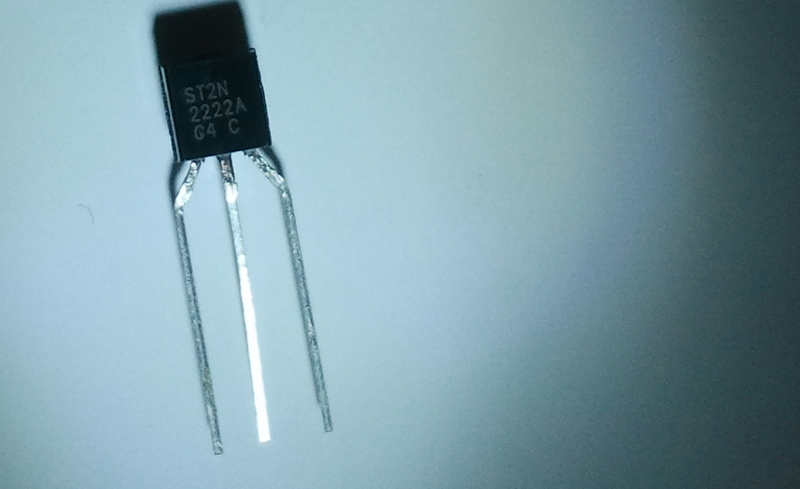 |
| 2N2222A |
 |
| Pin Mappings for 2N2222A |
E = Emitter
B = Base
C = Collector
The Emitter of a transistor is connected to ground, the device to be triggered is connected between the Collector of the transistor and SUPPLY. The transistor can be triggered by Supplying a Trigger voltage to the Base (preferably through a resistor). Depending upon the trigger voltage, Emitter and Collector of a transistor get in contact thereby allowing current flow through the device connected.
 |
| Buzzer - The Red Wire is Positive & The Blue Wire is Negative. |
 |
| First Setup the Transistor Side like in the Image |
 |
| The Blue wire going to the Collector here is the Negative of the Buzzer and the Red wire (the Positive of the Buzzer ) is connected to the '+'ve terminal of the Breadboard |
 |
| Now Connect a Wire from the Other end of the Resistor to the 7th pin (digital) of the Arduino |
 |
| Here is how the Final Setup Looks Like |
/*
  Pressing the Button changes the current active color of the RGB LED & prints the current temperature value to the Serial Monitor and Generates a Buzzer tone
  for the duration the button is being pressed.
  The light intensity detected by the LDR determines the intensity level of the active color
 */

int intensity = 0, pin = 9;

void setup() {
pinMode(2,INPUT);
pinMode(7,OUTPUT);
Serial.begin(9600);
}

void loop() {

  if(digitalRead(2)==0) // Switch being pressed
  {
    digitalWrite(7,HIGH);
    Serial.print("Temperature is : ");
    int temp = analogRead(2)/2;
    Serial.println(temp);
     if(pin<11)
        pin++;
      else
        pin=9;
     analogWrite(9,0);
     analogWrite(10,0);
     analogWrite(11,0);
  while(digitalRead(2)==0);
  delay(100);
  digitalWrite(7,LOW);
  }
  intensity = analogRead(4)/4;
  analogWrite(pin,intensity);
  Serial.print(pin);
  Serial.print("   ");
  Serial.println(intensity);
}
With that we come to the end of the first part of this tutorial.
very nice tutorial. great for starters...
ReplyDeleteThis is the clearest tutorial on ARDUINO that I have ever come across. It will be my pleasure to guide anyone starting in this fascinating hobby to visit your site. Thank you!
ReplyDelete