Simple Labs' Quick Start Kit for Arduino - Getting Started - Part II
This is the second part of a
multi-part tutorial that we are working on for you to get started with
the Simple Labs Quick Start kit for Arduino. In case you have not read the earlier part, you can check it out here = > Simple Labs' Quick Start Kit for Arduino - Getting Started - Part I
In this part, we will see
how to connect the following components of the Quick Start Kit and
Program for them using the Arduino. We will not delve into arduino
programming as this has been covered again and again.
IC ULN2003 - Replacing the Transistor
IR Proximity Sensor
LCD
DS1307 RTC
TSOP - Remote Control Receiver
7-Segment LED Display
We will stick to our previous method, we will choose a simple activity for each element and
keep adding to the previous activity. Keep in mind we are saying
activity and not project as we are not building any project of great
significance, we are rather focusing on 'how to'. You are expected to go
step by step through the activities as some of the coding might build
on the previous activity. So , Lets get started!
Download the following zip file with the source code for all these examples. Quick_Start_Kit.zip
We hope you have kept the basic breadboard setup intact and removed everything else from the previous experiments. Here's how your breadboard should look now.
Basic Breadboard Setup
IC ULN2003 - Darlington Pair Transistor Array
In our last example of the first part, we saw how to use a transistor to trigger a buzzer. What if we had more than one buzzer? We can't be setting up multiple transistors as that would get hectic. IC ULN2003 has an array of transistors built inside it and these transistors can be used very much like our regular transistor. The ULN2003 has 7 darlington pairs of transistors inside it. A darlington transistor pair is a cascading transistor setup that given an increased amplification. (Click Here to Read more on Darlington Pairs) Each of these pairs can drive a device and can be controlled individually.
Pin Diagram of ULN2003 / COM is +5V in our case
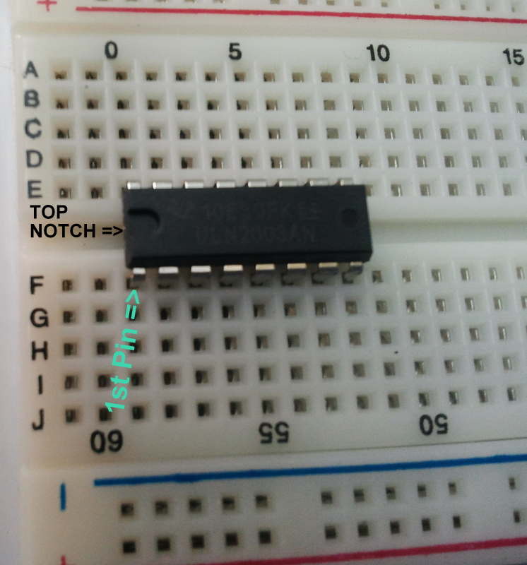
Place the ULN2003 IC as shown. The Top of All ICs is marked by a notch. The Pin to the LEFT of this Notch is the first pin of the IC. For Some IC's there will be a small dot next to the first pin.
Connect a wire from the '-'ve terminal to the 8th pin of the IC
Connect a wire between the 9th pin of the IC to the '+'ve terminal
Now Connect the Positive of the Buzzer (the Red Wire) to the '+'ve terminal and the Negative of the Buzzer to the 16th pin of the IC (OUTPUT 1)
Connect a Wire from GND on the Arduino to the '-'ve Terminal of the Breadboard
Connect a Wire from the 5V pin on the Arduino to the '+'ve terminal on the Breadboard
Connect a Wire from the 7th Pin of the Arduino to the 1st Pin of the ULN2003 [the Input1 Pin]
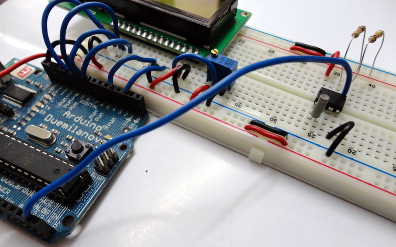
Here's how your final set up would look like!
Try the following code. A simple program - call it an audio_blink ;) [ULN_Buzzer.ino]
/*ULN2003- BuzzerThis program drives a Buzzer using ULN2003 */voidsetup()
{
pinMode(7,OUTPUT);
}
voidloop()
{
digitalWrite(7,HIGH);
delay(2000);
digitalWrite(7,LOW);
delay(3000);
}
The IR Proximity Sensor
The IR Proximity sensor is one of the most commonly used sensors. You will find these in automatic taps, automatic door opening, etc. This sensor works on the principle of IR reflectance. There is an IR LED (white / light blue in color) that is constantly emitting IR light. The light when reflected back falls on the IR Receiver LED / Photodiode (the black / dark blue color led). This received signal is then processed by an Op-Amp and the Op-Amp gives a HIGH signal. So the sensor module will give a HIGH signal if there is an object in front of the LED's. The range of sensing can be varied by adjusting the potentiometer on the sensor module. The maximum range of this module is only a few cms, so don't expect to use this as a distance sensor ;). The module will not work when pointed at black objects as black color tends to absorb the IR light.
Note: The IR Sensor and its 3-pin cable will not come attached. You need to fix the Cable on to the Sensor. There is only 1 way the cable will fit on the sensor module, so, we presume you can't go wrong about it ;)
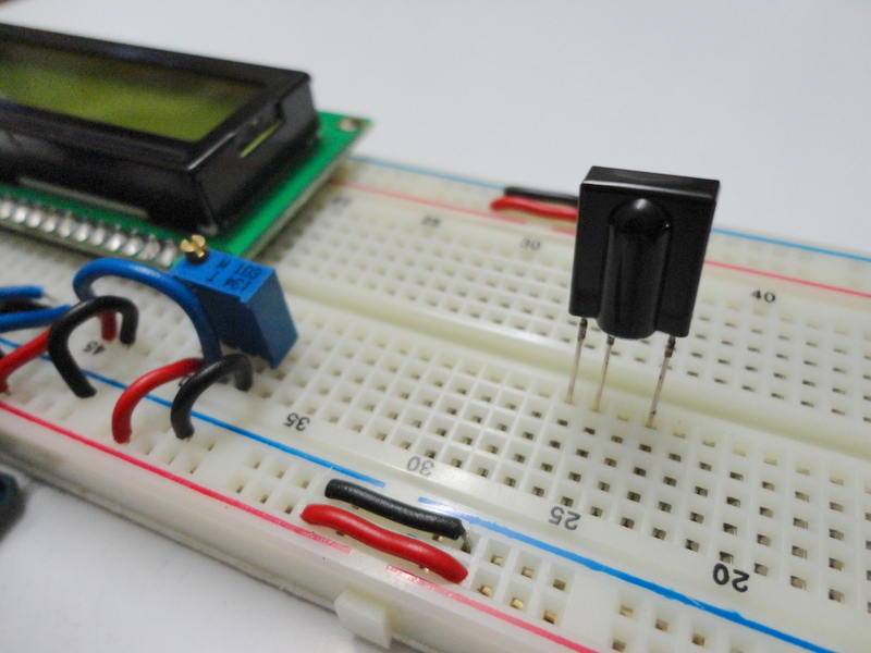
The IR Sensor. Look at the Wires and Their Mappings. We will connect these accordingly
Connect the Red Wire of the IR sensor to the '+'ve Terminal & the Black Wire of the IR sensor to the '-'ve Terminal
Connect the Brown wire of the IR sensor to the 8th pin of the Arduino
This is how your final setup should look like
Lets program to trigger the Buzzer everytime the sensor gives a HIGH signal. Try the following program. [ULN_Buzzer_IR.ino]
/*ULN2003- BuzzerThis program drives a Buzzer using ULN2003 */voidsetup()
{
pinMode(7,OUTPUT);
}
voidloop()
{
digitalWrite(7,HIGH);
delay(2000);
digitalWrite(7,LOW);
delay(3000);
}
LCD - Liquid Crystal Display
LCDs are commonly used display devices that you would find in most appliances / electronic devices. Your music players, Pay phones, Etc.
First Connect A Wire between the GND pin of the Arduino and the '-'ve terminal. Then Connect Another Wire from the 5V pin of the Arduino to the '+'ve terminal.
Place the LCD on the Breadboard as Shown (the 16th pin of the LCD is in the LEFT Corner of the Image)
This is what you should have now
Place the Trimpot Next to the LCD as shown (a bit away from the LCD pins)
Connect the Supply & Ground Lines for the Trimpot
The First and Last pins of the LCD are GND pins. First Connect a Wire from the 1st pin of the LCD to the '-'ve terminal
Connect a wire from the 16th pin of the LCD to the '-'ve terminal
The 2nd & 15th Pins of the LCD are Supply Pins, Connect Wires from these to the '+'ve Terminal as shown
The 5th of the LCD is the RW pin. This pin is used to toggle between Read / Write Mode of the LCD. Writing a HIGH signal to this pin corresponds to Read Mode and Writing a LOW signal corresponds to Write Mode. Since we will be using only the Write mode, we can wire this pin to GND / '-'ve terminal [This is equivalent of writing a LOW signal to the pin]
Connect a Wire from the middle pin of the trimpot to the 3rd pin of the LCD. The 3rd pin of the LCD is the contrast pin and the contrast of the display can be varied by varying the trimpot
Connect a Wire between the RS pin of the LCD (4th pin) and digital pin 2 of the Arudino. The RS pin helps select between the 2 registers of an LCD - Data & Command - for communication
Connect a wire between the Enable pin (the 6th pin) of the LCD and digital pin 4 of the Arduino
Connect a Wire between D4 of the LCD (11th pin) and digital pin 8 of the Arduino
Connect a Wire between D5 of the LCD (12th pin) and digital pin 9 of the Arduino
Connect a Wire between D6 of the LCD (13th pin) and digital pin 10 of the Arduino
Connect a Wire between D7of the LCD (14th pin) and digital pin 11 of the Arduino
The Finished Setup
Sample Hello World Program
So Lets program the LCD. We can take the sample hello world program found under File -> Examples -> LiquidCrystal menu of Arduino IDE and change the pin numbers in the following statement
From
LiquidCrystal lcd(12, 11, 5, 4, 3, 2);
To
LiquidCrystal lcd(2,4,8,9,10,11);
####IMPORTANT - IN CASE NOTHING IS DISPLAYED ON THE LCD KEEP VARYING THE TRIMPOT TILL YOU CAN SEE THE CHARACTERS###
Try the following Simple LCD program [Simple_LCD.ino]
/* LiquidCrystal Library - Hello World Demonstrates the use a 16x2 LCD display. The LiquidCrystal library works with all LCD displays that are compatible with the Hitachi HD44780 driver. There are many of them out there, and you can usually tell them by the 16-pin interface.*/// include the library code:
#include <LiquidCrystal.h>
// initialize the library with the numbers of the interface pinsLiquidCrystal lcd(2,4,8,9,10,11);
voidsetup() {
// set up the LCD's number of columns and rows:
lcd.begin(16, 2);
// Print a message to the LCD.
lcd.print("hello, world!");
}
voidloop() {
// set the cursor to column 0, line 1// (note: line 1 is the second row, since counting begins with 0):
lcd.setCursor(0, 1);
// print the number of seconds since reset:
lcd.print(millis()/1000);
}
DS1307 - Real Time Clock IC
The DS1307 lets you explore I2C communication on the arduino.
I2C Communication
I2C is short form for 'Inter Integrated Circuit' I2C Communication is Communication Bus standard developed by Phillips for standardising Communication between Integrated Circuits. For Eg. In a circuit, there could be a number of ICs each offering specific functionality[RTC, Temperature Sensor, EEPROM, etc] and they can all communicate on a single I2C Bus and provide combined functionalities. Each device on the I2C Bus would have a unique address by which it can be addressed.
Here's an Interesting Introduction from NXP
I2C on Arduino
The I2C Bus uses 2 lines for Communication - SDA(Serial Data) & SCL (Serial Clock). On the InduinoX / Arduino, these are available on SDA (Analog Input 4) & SCL (Analog Input 5). The I2C bus can be accessed using the 'Wire' Library of Arduino. First, lets try out a Library
Wiring up the DS1307
DS1307 Pin Mappings. SDA [Serial Data] / SCL [Serial Clock] correspond to lines for I2C Communication. We can ignore Vbat & SQW / OUT Pins.
Components - DS1307, Crystal for DS1307, 2 x 10K Resistors
Place the DS1307 IC as shown
Connect a Wire from the 4th pin of DS1307 (GND) to the '-'ve terminal
Connect a Wire from the 8th pin of DS1307 (+5V) to the '+'ve terminal
Place the Cyrstal as shown between the 1st and 2nd pin of the DS1307 IC- There is no polarity ('+' / '-' ve) for the crystal. So you can place it anyway
Place one resistor between the SDA Pin and the '+'ve terminal and one resistor between the SCL Pin and the '-'ve terminal
Connect a Wire between the SDA pin (pin5 of DS1307) and the SDA pin of the Arduino (Analog IN 4)
Connect a Wire between the SCL pin (pin6 of DS1307) and the SCL pin of the Arduino (Analog IN 5)
Final Setup with output from the following program
Try following Sample Program [LCD_RTC.ino]
/*This program uses the Wire Library (for i2c communication)This program sets the initial time for the RTC and keeps updating the time on an LCD everysecond.*/
#include <Wire.h>
#define rtc 0x68 // The pre-defined address for DS1307int ss,mm,hh,d,DD,MM,YY,mode;
boolean time_format,meridiem;
int prev;
#include <LiquidCrystal.h>
// initialize the library with the numbers of the interface pinsLiquidCrystal lcd(2,4,8,9,10,11);
voidsetup()
{
Wire.begin();
lcd.begin(16, 2);
set_time();
}
voidloop()
{
get_time();
if(ss!=prev) // lcd Print when the seconds change
{
lcd.setCursor(0,0);
lcd.print("Date:");
lcd.print(DD);
lcd.print("/");
lcd.print(MM);
lcd.print("/");
lcd.print(YY);
lcd.setCursor(0,1);
lcd.print("Time:");
lcd.print(hh);
lcd.print(":");
lcd.print(mm);
lcd.print(":");
lcd.print(ss);
prev=ss;
}
}
void get_time()
{
Wire.beginTransmission(rtc); // start communication over i2c with DS1307
Wire.write((byte)0); // Write the value of the register to point to
Wire.endTransmission(); // End communication over i2c with DS1307
Wire.requestFrom(rtc,7); // This will request 7 bytes of data
//starting from the '0' the register
ss=bcd_to_dec(Wire.read());
mm=bcd_to_dec(Wire.read());
hh=Wire.read();
time_format=hh&(1<<6);
meridiem=hh&(1<<5); // calculate am or pm
hh=bcd_to_dec(hh&0x1F);
d=bcd_to_dec(Wire.read());
DD=bcd_to_dec(Wire.read());
MM=bcd_to_dec(Wire.read());
YY=bcd_to_dec(Wire.read());
Wire.endTransmission();
}
void set_time()
{
time_format=0; // 0=24 hour mode, 1=12 hour mode
meridiem=1; // 0=am, 1=pm will not be taken into consideration if time format is 24 hour mode
mode=(time_format<<6)+((time_format&&meridiem)<<5); //calculate the bits to be added for 12 hour mode Wire.beginTransmission(rtc);
Wire.write((byte)0);
Wire.write(dec_to_bcd(50)); // secondsWire.write(dec_to_bcd(59)); // minutesWire.write(mode+dec_to_bcd(11));// hoursWire.write(dec_to_bcd(3)); // day of the week, startin mondayWire.write(dec_to_bcd(21)); // dateWire.write(dec_to_bcd(12)); // monthWire.write(dec_to_bcd(11)); // yearWire.endTransmission();
}
int dec_to_bcd(int dec)
{
return dec/10*16 + (dec%10);
}
int bcd_to_dec(int bcd)
{
return bcd/16*10 + (bcd%16);
}
TSOP - IR Receiver
The TSOP SM0038 is an IR receiver. The TSOP will help you to interface your TV remote with the Arduino and in the Process learn the basics of Wireless Communication.
The TSOP outputs a constant HIGH signal when idle and as it receives data, it tends to invert the data. i.e when an IR LED is transmitting data onto the TSOP, everytime the IR led goes high, the TSOP will go LOW and vice versa. Remote control signals are often bytes of data that is encoded and transmitted by pulsing(switching ON & OFF the IR LED at a specific frequency) Most TV remote controls work at 32-40 Khz frequency and most receivers can receive this range.
Heres a link to a nice write up on different remote control protocols. lets first take a look how the Sony Remote Control Protocol Works. We stick to Sony as it is the easiest one to get started with. Read this before proceeding
Here's a basic outline of how the data is sent. Every time you press a button on a Sony remote control, it sends out a 13Bit data. The first bit is a start bit indicating there are 12 bits of data following it. The next 7 bits are the command bit which will vary depending upon the keys being pressed. The last 5 bits are the address bits which will the same for all buttons but vary for remote controls of different devices.
The black bars in the following image correspond to high signals (called marks) and the white spaces in between correspond to low signals (called spaces). The duration of the 'marks' varies according to the bit being transmitted. It is 2.4ms for the start bit, 1.2ms for HIGH bit and 0.6ms for LOW bit. The duration of the 'spaces' is a constant 0.6ms. Every mark is followed by a space. Any data can be converted to binary format and transmitted in this manner. In fact this is the basic form of all types of serial communication.
Technique to decode this signal train, would be to constantly monitor the TSOP pin[Digital 15] for its normal state and the moment it produces a low signal, measure the duration of the low signal. If the measured duration of the low signal is around 2ms then measure and store the duration for the next 12 bits of the incoming data. After storing the data, evaluate the duration and based on the duration convert the data to decimal / hexadecimal and use it in your application.
Before wiring the TSOP, remove the DS1307 part alone from the breadboard.
TSOP Pin Mappings
The TSOP 1738
Place the TSOP on the Breadboard as Shown
Connect a wire between the 1st pin of the TSOP and the '-'ve terminal
Connect a wire between the 2nd pin of the TSOP and the '+'ve terminal
Connect a Wire between the 3rd pin of the TSOP and digital pin 12 of the Arduino
A Closeup of the Previous step!
There is an interesting IR remote library that can help you read different remotes without any difficulty. [This is included in the zip file]
How to use Libraries in Arduino - An Overview
To use any library you download, unzip the downloaded file and copy its contents to the libraries folder inside your arduino directory. You can check the library by opening the arduino ide and going to Sketch -> Import Library Option, if your library is in the proper location, it will show up here. Next if there is an example provided with the library (it will be inside a folder called example inside the base folder of the library) it will show up under the libraries name in the File->Examples Menu. You should reopen Arduino for the library to show up.
Once you install the IRremote Library, You can try the example program, IRrecvDemo. This program will give you a serial output of the HEX code for each value corresponding to each button on a remote. We will be using the decimal value in our next program. To get the decimal value, just do the following modification
change this line
from int RECV_PIN = 11;
to
int RECV_PIN = 12; // we have the lcd using the 11th pin ;)
replace this line Serial.println(results.value, HEX);
with Serial.println(results.value);
Here is the modified code [TSOP_IRrecvDemo.ino]
/*
 * IRremote: IRrecvDemo - demonstrates receiving IR codes with IRrecv
 * An IR detector/demodulator must be connected to the input RECV_PIN.
 * Version 0.1 July, 2009
 * Copyright 2009 Ken Shirriff
 * http://arcfn.com
 */

#include <IRremote.h>

int RECV_PIN = 12;

IRrecv irrecv(RECV_PIN);

decode_results results;
int remote = 0;
voidsetup()
{
Serial.begin(9600);
irrecv.enableIRIn(); // Start the receiver
}
voidloop() {
if (irrecv.decode(&results)) {
    remote = results.value;
    Serial.println(remote);
    irrecv.resume(); // Receive the next value
  }
}
Now get your remote and make note of the values you get for pressing various buttons.
Now lets try to display the remote button value on the LCD. [LCD_TSOP.ino]
/*The following program uses the IRremote library and displays the value of the button being pressed on the LCD*/
#include <IRremote.h>
#include <LiquidCrystal.h>
/*List of Values corresponding to numbers of the remote being pressed, remember to replace these values with the values you get.1 162 20643 10404 30885 5286 25767 29608 36009 2720 2320*/// initialize the library with the numbers of the interface pinsLiquidCrystal lcd(2,4,8,9,10,11);
int RECV_PIN = 12;
IRrecv irrecv(RECV_PIN);
decode_results results;
int remote = 0, display_value=0;
voidsetup()
{
lcd.begin(16,2);
irrecv.enableIRIn(); // Start the receiver
}
voidloop() {
if (irrecv.decode(&results)) {
remote = results.value;
switch(remote)
{
case 16 : display_value=1; break;
case 2064 : display_value=2; break;
case 1040 : display_value=3; break;
case 3088 : display_value=4; break;
case 528 : display_value=5; break;
case 2576 : display_value=6; break;
case 2960 : display_value=7; break;
case 3600 : display_value=8; break;
case 272 : display_value=9; break;
case 2320 : display_value=0; break;
}
lcd.clear();
lcd.print(display_value);
irrecv.resume(); // Receive the next value
}
}
The 7-Segment Display
7-Segment displays are another common component in the world of electronics. These displays have 8 LEDs split into different segments designed to be able to display numerals from 0-9 and a dot. All The LEDs have a common ground / supply line. There are 5 pins at the top and 5 pins at the bottom. The middle pins in the top and bottom are connected to each other internally and have to be connected to Ground / Supply depending upon the type of the 7-segment Display. You can control each segment like an individual LED. However, this method of controlling the 7-segment LED to display numbers would be hectic. So, we will use a technique called Port Manipulation. Pins on the Arduino are grouped together as a PORT. You can control a whole PORT at a time. Read the following write up on the Arduino website before you proceed => Port Manipulation
The 7-Segment Display included in the starter kit is a Common Cathode Type.
7 - Segment LED
Segment & Pin Mapping of a 7-Segment LED / We will be connecting segments A-G & P to digital pins 0-6 & 7 of the Arduino
Place the 7-segment Display on the Breadboard.
Place a 1K resistor between the middle pin on the top and the '-'ve terminal
Connect a Wire from Segment A to digital pin 0 of the Arduino
Connect a Wire from Segment B to digital pin 1 of the Arduino
Connect a Wire from Segment C to digital pin 2 of the Arduino
Connect a Wire from Segment D to digital pin 3 of the Arduino
Connect a Wire from Segment E to digital pin 4 of the Arduino
Connect a Wire from Segment F to digital pin 5 of the Arduino
Connect a Wire from Segment G to digital pin 6 of the Arduino
Connect a Wire from Segment P to digital pin 7 of the Arduino
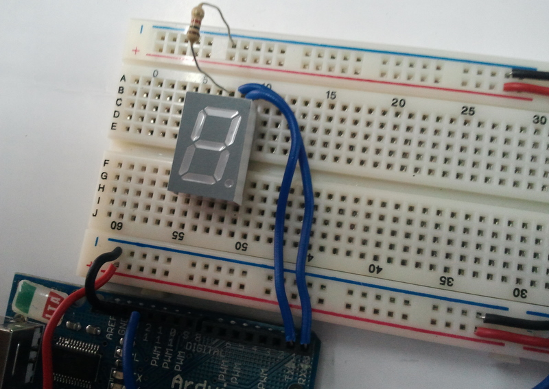
Our Final Setup with a Program
First Try the following program that cycles from digits 0 - 9. [SEV_SEG.ino]
/*This is to Display numbers 0-9 on the seven segment LED*//*Wiring Seg A - Pin 0Seg B - Pin 1Seg C - Pin 2Seg D - Pin 3Seg E - Pin 4Seg F - Pin 5Seg G - Pin 6Seg H - Pin 7*//*To Display '0' we need to make high All Segments except G & Hbased on this lets make a list of values to write to port D [pins 0-7 are grouped together as port D]When we write a binary value to the port the MSB or the 8th bit will be written to pin 7 and the lsb will be written to pin 00 => B001111111 => B000001102 => B010110113 => B010011114 => B011001105 => B011011016 => B011111017 => B000001118 => B011111119 => B01101111*/int val[]={B00111111,B00000110,B01011011,B01001111,B01100110, B01101101,B01111101, B00000111, B01111111, B01101111};
voidsetup()
{
DDRD = B11111111;
}
voidloop()
{
for(int i=0; i<10;i++)
{
PORTD = val[i];
delay(1000);
}
}
Now Try the following program - An extension of our Remote Control Program. Here the Value of the Button being pressed is displayed on the 7-segment display. [SEV_SEG_TSOP.ino]
/*This is to Display numbers 0-9 on the seven segment LED based on Remote Control INPUT*//*Wiring Seg A - Pin 0Seg B - Pin 1Seg C - Pin 2Seg D - Pin 3Seg E - Pin 4Seg F - Pin 5Seg G - Pin 6Seg H - Pin 7*//*To Display '0' we need to make high All Segments except G & Hbased on this lets make a list of values to write to port D [pins 0-7 are grouped together as port D]When we write a binary value to the port the MSB or the 8th bit will be written to pin 7 and the lsb will be written to pin 00 => B001111111 => B000001102 => B010110113 => B010011114 => B011001105 => B011011016 => B011111017 => B000001118 => B011111119 => B01101111*/
#include <IRremote.h>
int RECV_PIN = 12;
IRrecv irrecv(RECV_PIN);
decode_results results;
int remote = 0, display_value=0;
int val[]={B00111111,B00000110,B01011011,B01001111,B01100110, B01101101,B01111101, B00000111, B01111111, B01101111};
voidsetup()
{
DDRD = B11111111; // Declares PORT D as Output, PORTD is digital pins 0-7
irrecv.enableIRIn(); // Start the receiver
}
voidloop()
{
if (irrecv.decode(&results)) {
remote = results.value;
switch(remote)
{
case 16 : display_value=1; break;
case 2064 : display_value=2; break;
case 1040 : display_value=3; break;
case 3088 : display_value=4; break;
case 528 : display_value=5; break;
case 2576 : display_value=6; break;
case 2960 : display_value=7; break;
case 3600 : display_value=8; break;
case 272 : display_value=9; break;
case 2320 : display_value=0; break;
}
PORTD = val[display_value];
irrecv.resume(); // Receive the next value
}
}


No comments:
Post a Comment