The 7-Segment Display
7-Segment displays are another common component in the world of electronics. These displays have 8 LEDs split into different segments designed to be able to display numerals from 0-9 and a dot. All The LEDs have a common ground / supply line. There are 5 pins at the top and 5 pins at the bottom. The middle pins in the top and bottom are connected to each other internally and have to be connected to Ground / Supply depending upon the type of the 7-segment Display. You can control each segment like an individual LED. However, this method of controlling the 7-segment LED to display numbers would be hectic. So, we will use a technique called Port Manipulation. Pins on the Arduino are grouped together as a PORT. You can control a whole PORT at a time. Read the following write up on the Arduino website before you proceed => Port Manipulation
The 7-Segment Display included in the starter kit is a Common Cathode Type.
First Try the following program that cycles from digits 0 - 9. [SEV_SEG.ino]
Now Try the following program - An extension of our Remote Control Program. Here the Value of the Button being pressed is displayed on the 7-segment display. [SEV_SEG_TSOP.ino]
7-Segment displays are another common component in the world of electronics. These displays have 8 LEDs split into different segments designed to be able to display numerals from 0-9 and a dot. All The LEDs have a common ground / supply line. There are 5 pins at the top and 5 pins at the bottom. The middle pins in the top and bottom are connected to each other internally and have to be connected to Ground / Supply depending upon the type of the 7-segment Display. You can control each segment like an individual LED. However, this method of controlling the 7-segment LED to display numbers would be hectic. So, we will use a technique called Port Manipulation. Pins on the Arduino are grouped together as a PORT. You can control a whole PORT at a time. Read the following write up on the Arduino website before you proceed => Port Manipulation
The 7-Segment Display included in the starter kit is a Common Cathode Type.
 |
| 7 - Segment LED |
 |
| Segment & Pin Mapping of a 7-Segment LED / We will be connecting segments A-G & P to digital pins 0-6 & 7 of the Arduino |
 |
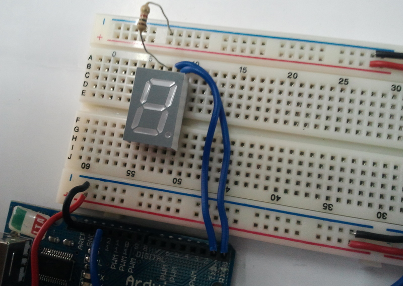
| Place the 7-segment Display on the Breadboard. |
 |
| Place a 1K resistor between the middle pin on the top and the '-'ve terminal |
 |
| Connect a Wire from Segment A to digital pin 0 of the Arduino |
 |
| Connect a Wire from Segment B to digital pin 1 of the Arduino |
 |
| Connect a Wire from Segment C to digital pin 2 of the Arduino |
 |
| Connect a Wire from Segment D to digital pin 3 of the Arduino |
 |
| Connect a Wire from Segment E to digital pin 4 of the Arduino |
 |
| Connect a Wire from Segment F to digital pin 5 of the Arduino |
 |
| Connect a Wire from Segment G to digital pin 6 of the Arduino |
 |
| Connect a Wire from Segment P to digital pin 7 of the Arduino |
 |
| Our Final Setup with a Program |
/*

This is to Display numbers 0-9 on the seven segment LED

*/

/*

Wiring
Seg A - Pin 0
Seg B - Pin 1
Seg C - Pin 2
Seg D - Pin 3
Seg E - Pin 4
Seg F - Pin 5
Seg G - Pin 6
Seg H - Pin 7

*/

/*
To Display '0' we need to make high All Segments except G & H
based on this lets make a list of values to write to port D [pins 0-7 are grouped together as port D]
When we write a binary value to the port the MSB or the 8th bit will be written to pin 7 and the lsb will be written to pin 0

0 => B00111111
1 => B00000110
2 => B01011011
3 => B01001111
4 => B01100110
5 => B01101101
6 => B01111101
7 => B00000111
8 => B01111111
9 => B01101111

*/

int val[]={B00111111,B00000110,B01011011,B01001111,B01100110, B01101101,B01111101, B00000111, B01111111, B01101111};

void setup()
{
  DDRD = B11111111;
}

void loop()
{
  for(int i=0; i<10;i++)
  {
    PORTD = val[i];
    delay(1000);
  }
}
Now Try the following program - An extension of our Remote Control Program. Here the Value of the Button being pressed is displayed on the 7-segment display. [SEV_SEG_TSOP.ino]
/*

This is to Display numbers 0-9 on the seven segment LED based on Remote Control INPUT

*/

/*

Wiring
Seg A - Pin 0
Seg B - Pin 1
Seg C - Pin 2
Seg D - Pin 3
Seg E - Pin 4
Seg F - Pin 5
Seg G - Pin 6
Seg H - Pin 7

*/

/*
To Display '0' we need to make high All Segments except G & H
based on this lets make a list of values to write to port D [pins 0-7 are grouped together as port D]
When we write a binary value to the port the MSB or the 8th bit will be written to pin 7 and the lsb will be written to pin 0

0 => B00111111
1 => B00000110
2 => B01011011
3 => B01001111
4 => B01100110
5 => B01101101
6 => B01111101
7 => B00000111
8 => B01111111
9 => B01101111

*/

#include <IRremote.h>

int RECV_PIN = 12;
IRrecv irrecv(RECV_PIN);
decode_results results;
int remote = 0, display_value=0;

int val[]={B00111111,B00000110,B01011011,B01001111,B01100110, B01101101,B01111101, B00000111, B01111111, B01101111};

void setup()
{
  DDRD = B11111111; // Declares PORT D as Output, PORTD is digital pins 0-7
  irrecv.enableIRIn(); // Start the receiver
}

void loop()
{
  if (irrecv.decode(&results)) {
    remote = results.value;
    switch(remote)
    {
      case 16 : display_value=1; break;
      case 2064 : display_value=2; break;
      case 1040 : display_value=3; break;
      case 3088 : display_value=4; break;
      case 528 : display_value=5; break;
      case 2576 : display_value=6; break;
      case 2960 : display_value=7; break;
      case 3600 : display_value=8; break;
      case 272 : display_value=9; break;
      case 2320 : display_value=0; break;
    }

    PORTD = val[display_value];
    irrecv.resume(); // Receive the next value

}
}
Very good, ty
ReplyDeleteHow do I connect multiple displays for a two or three digit display?
ReplyDeleteVery nice,
ReplyDeleteHow do I connect multiple displays for a two or three digit display?
Tnx.
Is it necessary to connect segment P to digital pin 7 of the arduino?. Because without connecting it the display works fine
ReplyDeleteyou gain expertise, It is extremely helpful for me.would you mind updating your blog with more information?
ReplyDeleteelectronic display boards india
you missed the power connections
ReplyDelete