Generating Sound - Buzzer + Transistor
Next
lets see how we can generate sound using a Buzzer. The Buzzer would
require more current than provided by the pins of the arduino. To
provide the buzzer with more current, we shall use a transistor to
trigger the buzzer. The transistor in turn will be triggered by a pin on
the arduino. If you do not know about transistors, its advisable you
check it out
http://en.wikipedia.org/wiki/Transistor
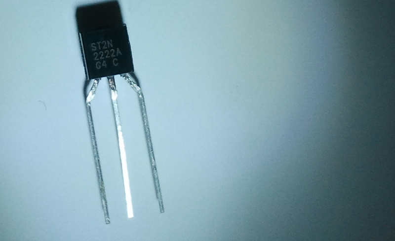
Here's what our Transistor 2N2222A looks like
 |
| 2N2222A |
 |
| Pin Mappings for 2N2222A |
E = Emitter
B = Base
C = Collector
The
Emitter of a transistor is connected to ground, the device to be
triggered is connected between the Collector of the transistor and
SUPPLY. The transistor can be triggered by Supplying a Trigger voltage
to the Base (preferably through a resistor). Depending upon the trigger
voltage, Emitter and Collector of a transistor get in contact thereby
allowing current flow through the device connected.
 |
| Buzzer - The Red Wire is Positive & The Blue Wire is Negative. |
 |
| First Setup the Transistor Side like in the Image |
 |
| The Blue wire
going to the Collector here is the Negative of the Buzzer and the Red
wire (the Positive of the Buzzer ) is connected to the '+'ve terminal of
the Breadboard |
 |
| Now Connect a Wire from the Other end of the Resistor to the 7th pin (digital) of the Arduino |
 |
| Here is how the Final Setup Looks Like |
Try the following code where the Buzzer stays on as
you keep pressing the Button in our previous program
[RGB_button_ldr_buzzer.ino]
/*
  Pressing the Button changes the current active color of the RGB LED & prints the current temperature value to the Serial Monitor and Generates a Buzzer tone
  for the duration the button is being pressed.
  The light intensity detected by the LDR determines the intensity level of the active color
 */

int intensity = 0, pin = 9;

void setup() {
pinMode(2,INPUT);
pinMode(7,OUTPUT);
Serial.begin(9600);
}

void loop() {

  if(digitalRead(2)==0) // Switch being pressed
  {
    digitalWrite(7,HIGH);
    Serial.print("Temperature is : ");
    int temp = analogRead(2)/2;
    Serial.println(temp);
     if(pin<11)
        pin++;
      else
        pin=9;
     analogWrite(9,0);
     analogWrite(10,0);
     analogWrite(11,0);
  while(digitalRead(2)==0);
  delay(100);
  digitalWrite(7,LOW);
  }
  intensity = analogRead(4)/4;
  analogWrite(pin,intensity);
  Serial.print(pin);
  Serial.print("   ");
  Serial.println(intensity);
}


Simple and Excellent
ReplyDeleteThis is fantastic work by you guys...truly appreciate the close up pics and detailed setup explanation
ReplyDelete