Simple Labs' Quick Start Kit for Arduino - DS1307 Real Time Clock IC Interfacing- How To?
DS1307 - Real Time Clock IC
The DS1307 lets you explore I2C communication on the arduino.
I2C Communication
I2C
is short form for 'Inter Integrated Circuit' I2C Communication is
Communication Bus standard developed by Phillips for standardising
Communication between Integrated Circuits. For Eg. In a circuit, there
could be a number of ICs each offering specific functionality[RTC,
Temperature Sensor, EEPROM, etc] and they can all communicate on a
single I2C Bus and provide combined functionalities. Each device on the
I2C Bus would have a unique address by which it can be addressed.
Here's an Interesting Introduction from NXP
I2C on Arduino
The
I2C Bus uses 2 lines for Communication - SDA(Serial Data) & SCL
(Serial Clock). On the InduinoX / Arduino, these are available on SDA
(Analog Input 4) & SCL (Analog Input 5). The I2C bus can be accessed
using the 'Wire' Library of Arduino. First, lets try out a Library
Wiring up the DS1307
DS1307 Pin
Mappings. SDA [Serial Data] / SCL [Serial Clock] correspond to lines for
I2C Communication. We can ignore Vbat & SQW / OUT Pins.
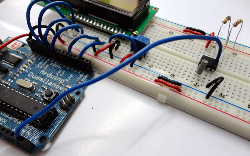
Components - DS1307, Crystal for DS1307, 2 x 10K Resistors
Place the DS1307 IC as shown
Connect a Wire from the 4th pin of DS1307 (GND) to the '-'ve terminal
Connect a Wire from the 8th pin of DS1307 (+5V) to the '+'ve terminal
Place the
Cyrstal as shown between the 1st and 2nd pin of the DS1307 IC- There is
no polarity ('+' / '-' ve) for the crystal. So you can place it anyway
Place one resistor between the SDA Pin and the '+'ve terminal and one resistor between the SCL Pin and the '+'ve terminal
Connect a Wire between the SDA pin (pin5 of DS1307) and the SDA pin of the Arduino (Analog IN 4)
Connect a Wire between the SCL pin (pin6 of DS1307) and the SCL pin of the Arduino (Analog IN 5)
Final Setup with output from the following program
Try following Sample Program [LCD_RTC.ino]
/*This program uses the Wire Library (for i2c communication)This program sets the initial time for the RTC and keeps updating the time on an LCD everysecond.*/
#include <Wire.h>
#define rtc 0x68 // The pre-defined address for DS1307int ss,mm,hh,d,DD,MM,YY,mode;
boolean time_format,meridiem;
int prev;
#include <LiquidCrystal.h>
// initialize the library with the numbers of the interface pinsLiquidCrystal lcd(2,4,8,9,10,11);
voidsetup()
{
Wire.begin();
lcd.begin(16, 2);
set_time();
}
voidloop()
{
get_time();
if(ss!=prev) // lcd Print when the seconds change
{
lcd.setCursor(0,0);
lcd.print("Date:");
lcd.print(DD);
lcd.print("/");
lcd.print(MM);
lcd.print("/");
lcd.print(YY);
lcd.setCursor(0,1);
lcd.print("Time:");
lcd.print(hh);
lcd.print(":");
lcd.print(mm);
lcd.print(":");
lcd.print(ss);
prev=ss;
}
}
void get_time()
{
Wire.beginTransmission(rtc); // start communication over i2c with DS1307
Wire.write((byte)0); // Write the value of the register to point to
Wire.endTransmission(); // End communication over i2c with DS1307
Wire.requestFrom(rtc,7); // This will request 7 bytes of data
//starting from the '0' the register
ss=bcd_to_dec(Wire.read());
mm=bcd_to_dec(Wire.read());
hh=Wire.read();
time_format=hh&(1<<6);
meridiem=hh&(1<<5); // calculate am or pm
hh=bcd_to_dec(hh&0x1F);
d=bcd_to_dec(Wire.read());
DD=bcd_to_dec(Wire.read());
MM=bcd_to_dec(Wire.read());
YY=bcd_to_dec(Wire.read());
Wire.endTransmission();
}
void set_time()
{
time_format=0; // 0=24 hour mode, 1=12 hour mode
meridiem=1; // 0=am, 1=pm will not be taken into consideration if time format is 24 hour mode
mode=(time_format<<6)+((time_format&&meridiem)<<5); //calculate the bits to be added for 12 hour mode Wire.beginTransmission(rtc);
Wire.write((byte)0);
Wire.write(dec_to_bcd(50)); // secondsWire.write(dec_to_bcd(59)); // minutesWire.write(mode+dec_to_bcd(11));// hoursWire.write(dec_to_bcd(3)); // day of the week, startin mondayWire.write(dec_to_bcd(21)); // dateWire.write(dec_to_bcd(12)); // monthWire.write(dec_to_bcd(11)); // yearWire.endTransmission();
}
int dec_to_bcd(int dec)
{
return dec/10*16 + (dec%10);
}
int bcd_to_dec(int bcd)
{
return bcd/16*10 + (bcd%16);
}
This code does not give a proper output. LCD displaying "--:--:--" instead of time and "-/-/----" instead of date. Checked the circuit and even tried copy-pasting the code given. And going by the images it seems you people edited the sketch before uploading here. Can you please upload the original sketch? I think thats were something must have gone wrong
Hi, Can you test it again? We have tested it 5 different times and it works every time... excepting when there is a grounding issue... check your ground connections and kindly update us.
I have the same problem, lcd print "-1/-1/-1" ,but when I was touch to "BAT" pin on my DS1307 module, it started count time. It was maybe needed short pulse on this pin.
Hi, Can you test it again? We have tested it 5 different times and it works every time... excepting when there is a grounding issue... check your ground connections and kindly update us.
this code is giving a proper output with the defined format but the only problm i am facing is in the count of seconds which after 59 increments as 059 159 259 359... and so on please guide regarding the mentioned problem....
If you are facing issues with the DS1307, check your grounding connection and check your power source. We have observed that at times when a board is powered from USB, this does happen randomly. kindly mail us incase of any difficulty


The program is not giving a proper output. Any solutions?
ReplyDeleteI have already checked the circuit connections and they are as per the images.
What is the output you are getting? Kindly share detailed information as otherwise it might be difficult to support..
DeleteThis code does not give a proper output. LCD displaying "--:--:--" instead of time and "-/-/----" instead of date. Checked the circuit and even tried copy-pasting the code given. And going by the images it seems you people edited the sketch before uploading here. Can you please upload the original sketch? I think thats were something must have gone wrong
ReplyDeleteHi, Can you test it again? We have tested it 5 different times and it works every time... excepting when there is a grounding issue... check your ground connections and kindly update us.
DeleteI have the same problem, lcd print "-1/-1/-1" ,but when I was touch to "BAT" pin on my DS1307 module, it started count time. It was maybe needed short pulse on this pin.
ReplyDeleteHi, Can you test it again? We have tested it 5 different times and it works every time... excepting when there is a grounding issue... check your ground connections and kindly update us.
DeleteEven i face the same issue.
ReplyDeletei have the same problem please help fast
ReplyDeleteYep, this circuit doesnt work. Even Im getting the same error as described above!
ReplyDeletethis code is giving a proper output with the defined format but the only problm i am facing is in the count of seconds which after 59 increments as 059 159 259 359... and so on
ReplyDeleteplease guide regarding the mentioned problem....
"Place one resistor between the SDA Pin and the '+'ve terminal and one resistor between the SCL Pin and the '-'ve terminal"
ReplyDeleteMay be this information is misleading to those who had problem. It should be SCL Pin and +ve terminal. Both SDA and SCL should be pulled up.
Thanks! We have updated it Now
DeleteDear All,
ReplyDeleteIf you are facing issues with the DS1307, check your grounding connection and check your power source. We have observed that at times when a board is powered from USB, this does happen randomly. kindly mail us incase of any difficulty
LCD shows date:-1/-1/-1
ReplyDeleteTime:25/-1/-1
does not works
MAN this code worked great!! THANKS
ReplyDeleteSame.. LCD shows
ReplyDeleteDate:-1/-1/-1
Time:25:-1:-1
Same.. LCD shows
ReplyDeleteDate:-1/-1/-1
Time:25:-1:-1