The 7-Segment Display
7-Segment displays are another common component in the world of electronics. These displays have 8 LEDs split into different segments designed to be able to display numerals from 0-9 and a dot. All The LEDs have a common ground / supply line. There are 5 pins at the top and 5 pins at the bottom. The middle pins in the top and bottom are connected to each other internally and have to be connected to Ground / Supply depending upon the type of the 7-segment Display. You can control each segment like an individual LED. However, this method of controlling the 7-segment LED to display numbers would be hectic. So, we will use a technique called Port Manipulation. Pins on the Arduino are grouped together as a PORT. You can control a whole PORT at a time. Read the following write up on the Arduino website before you proceed => Port Manipulation
The 7-Segment Display included in the starter kit is a Common Cathode Type.
First Try the following program that cycles from digits 0 - 9. [SEV_SEG.ino]
Now Try the following program - An extension of our Remote Control Program. Here the Value of the Button being pressed is displayed on the 7-segment display. [SEV_SEG_TSOP.ino]
7-Segment displays are another common component in the world of electronics. These displays have 8 LEDs split into different segments designed to be able to display numerals from 0-9 and a dot. All The LEDs have a common ground / supply line. There are 5 pins at the top and 5 pins at the bottom. The middle pins in the top and bottom are connected to each other internally and have to be connected to Ground / Supply depending upon the type of the 7-segment Display. You can control each segment like an individual LED. However, this method of controlling the 7-segment LED to display numbers would be hectic. So, we will use a technique called Port Manipulation. Pins on the Arduino are grouped together as a PORT. You can control a whole PORT at a time. Read the following write up on the Arduino website before you proceed => Port Manipulation
The 7-Segment Display included in the starter kit is a Common Cathode Type.
 |
| 7 - Segment LED |
 |
| Segment & Pin Mapping of a 7-Segment LED / We will be connecting segments A-G & P to digital pins 0-6 & 7 of the Arduino |
 |
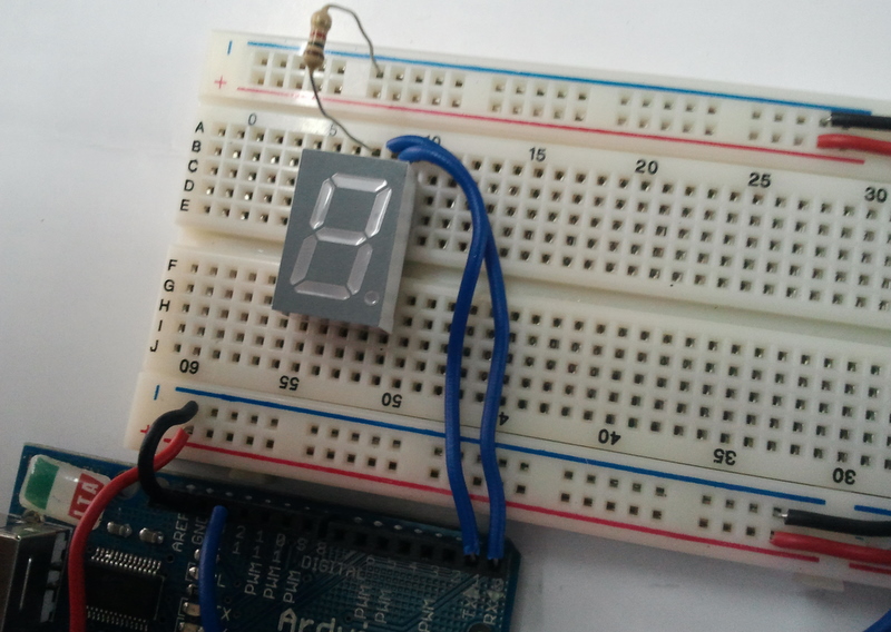
| Place the 7-segment Display on the Breadboard. |
 |
| Place a 1K resistor between the middle pin on the top and the '-'ve terminal |
 |
| Connect a Wire from Segment A to digital pin 0 of the Arduino |
 |
| Connect a Wire from Segment B to digital pin 1 of the Arduino |
 |
| Connect a Wire from Segment C to digital pin 2 of the Arduino |
 |
| Connect a Wire from Segment D to digital pin 3 of the Arduino |
 |
| Connect a Wire from Segment E to digital pin 4 of the Arduino |
 |
| Connect a Wire from Segment F to digital pin 5 of the Arduino |
 |
| Connect a Wire from Segment G to digital pin 6 of the Arduino |
 |
| Connect a Wire from Segment P to digital pin 7 of the Arduino |
 |
| Our Final Setup with a Program |
/*

This is to Display numbers 0-9 on the seven segment LED

*/

/*

Wiring
Seg A - Pin 0
Seg B - Pin 1
Seg C - Pin 2
Seg D - Pin 3
Seg E - Pin 4
Seg F - Pin 5
Seg G - Pin 6
Seg H - Pin 7

*/

/*
To Display '0' we need to make high All Segments except G & H
based on this lets make a list of values to write to port D [pins 0-7 are grouped together as port D]
When we write a binary value to the port the MSB or the 8th bit will be written to pin 7 and the lsb will be written to pin 0

0 => B00111111
1 => B00000110
2 => B01011011
3 => B01001111
4 => B01100110
5 => B01101101
6 => B01111101
7 => B00000111
8 => B01111111
9 => B01101111

*/

int val[]={B00111111,B00000110,B01011011,B01001111,B01100110, B01101101,B01111101, B00000111, B01111111, B01101111};

void setup()
{
  DDRD = B11111111;
}

void loop()
{
  for(int i=0; i<10;i++)
  {
    PORTD = val[i];
    delay(1000);
  }
}
Now Try the following program - An extension of our Remote Control Program. Here the Value of the Button being pressed is displayed on the 7-segment display. [SEV_SEG_TSOP.ino]
/*

This is to Display numbers 0-9 on the seven segment LED based on Remote Control INPUT

*/

/*

Wiring
Seg A - Pin 0
Seg B - Pin 1
Seg C - Pin 2
Seg D - Pin 3
Seg E - Pin 4
Seg F - Pin 5
Seg G - Pin 6
Seg H - Pin 7

*/

/*
To Display '0' we need to make high All Segments except G & H
based on this lets make a list of values to write to port D [pins 0-7 are grouped together as port D]
When we write a binary value to the port the MSB or the 8th bit will be written to pin 7 and the lsb will be written to pin 0

0 => B00111111
1 => B00000110
2 => B01011011
3 => B01001111
4 => B01100110
5 => B01101101
6 => B01111101
7 => B00000111
8 => B01111111
9 => B01101111

*/

#include <IRremote.h>

int RECV_PIN = 12;
IRrecv irrecv(RECV_PIN);
decode_results results;
int remote = 0, display_value=0;

int val[]={B00111111,B00000110,B01011011,B01001111,B01100110, B01101101,B01111101, B00000111, B01111111, B01101111};

void setup()
{
  DDRD = B11111111; // Declares PORT D as Output, PORTD is digital pins 0-7
  irrecv.enableIRIn(); // Start the receiver
}

void loop()
{
  if (irrecv.decode(&results)) {
    remote = results.value;
    switch(remote)
    {
      case 16 : display_value=1; break;
      case 2064 : display_value=2; break;
      case 1040 : display_value=3; break;
      case 3088 : display_value=4; break;
      case 528 : display_value=5; break;
      case 2576 : display_value=6; break;
      case 2960 : display_value=7; break;
      case 3600 : display_value=8; break;
      case 272 : display_value=9; break;
      case 2320 : display_value=0; break;
    }

    PORTD = val[display_value];
    irrecv.resume(); // Receive the next value

}
}

